Foundation design is not a one-size-fits-all discipline. The choice between a raft foundation, strip foundation, pile foundation, or pad foundation directly shapes the safety, cost, and longevity of every structure — from a modest residential villa to a high-rise commercial tower. Getting this decision wrong can mean differential settlement, structural cracking, or catastrophic failure. Getting it right means a building that performs exactly as designed for decades.
At TechVisionEra Engineering, our structural team evaluates dozens of variables before recommending a foundation system: soil bearing capacity, groundwater depth, imposed loads, seismic zone classification, and client budget. This expert guide breaks down the four primary foundation types — shallow and deep — the ground conditions that favour each, and the engineering logic that drives the selection process, whether your project is in Syria, Saudi Arabia, the UAE, or anywhere across the MENA region and beyond.
Why Foundation Selection Determines Structural Success
The foundation is the silent load-bearer beneath every wall, column, and slab. It transfers the full dead, live, and dynamic loads of a structure into the ground — and if the ground pushes back harder than expected, or shifts under seismic or hydrostatic pressure, the consequences propagate upward through the entire building frame. Foundation failure is rarely visible until it is irreversible: a subtle crack in a masonry wall, a door that no longer closes flush, a floor that tilts by a fraction of a degree — these are the early warnings of ground movement that, left uncorrected, can compromise structural integrity entirely.
Soil investigation is the mandatory first step. A geotechnical report — covering Standard Penetration Tests (SPTs), cone penetration tests (CPTs), bore logs, and laboratory analysis of soil samples — quantifies the allowable bearing capacity of the underlying strata. This figure, typically expressed in kN/m², is the primary input that determines whether a shallow foundation is viable or whether deep foundations are required. Secondary inputs include the depth to groundwater, the presence of compressible layers such as peat or loose fill, the potential for soil liquefaction under seismic loading, and the proximity of adjacent structures whose existing foundations may be affected by new excavation or dewatering operations.
Eurocode 7 (EN 1997), the international standard governing geotechnical design, requires engineers to evaluate both the Ultimate Limit State (ULS) and the Serviceability Limit State (SLS). The ULS check ensures the ground will not fail under maximum factored load; the SLS check verifies that total and differential settlements remain within acceptable limits for the structure's intended use. A hospital or data centre has far more stringent differential settlement limits than an industrial warehouse. TechVisionEra Engineering applies Eurocode 7 across all international projects, supplemented by local codes — including the Saudi Building Code (SBC), Abu Dhabi International Building Code (ADIBC), and Jordanian engineering standards — wherever national requirements apply.
Pad Foundations — Efficient Solutions for Isolated Column Loads
Also called isolated footings or spread footings, pad foundations are the simplest and most economical foundation type for structures with clearly defined column grids. Each pad sits directly beneath a single column or structural pier, spreading the concentrated point load over a larger area of ground. The geometry is typically square or rectangular in plan, with depth determined by the need to reach competent soil and to develop the required punching shear resistance in the concrete section.
Pad foundations perform best when soil bearing capacity is moderate to high — typically above 75–100 kN/m² — and when columns are spaced far enough apart that their pressure bulbs in the soil do not overlap significantly. Common applications include steel-framed industrial buildings, portal frame warehouses, single-storey retail pavilions, and the column bases of multi-storey reinforced concrete frames on competent soil. Where ground conditions are uniform and well understood, pad foundations deliver the lowest material cost and the fastest construction programme of any foundation system — making them the default preference where ground conditions allow.
The design process begins with calculating the net column load — dead plus imposed plus wind, factored for the governing load combination under Eurocode 0 — then sizing the pad plan dimensions so that the applied bearing pressure stays within the allowable limit from the geotechnical report. Reinforcement is designed to resist the bending moments and punching shear induced by the upward soil reaction. In BIM-driven workflows, pad geometry, reinforcement, and soil data are linked parametrically — any change in column load automatically updates the footing schedule. TechVisionEra's structural engineering team delivers detailed footing schedules and reinforcement drawings fully coordinated within Revit models, eliminating discrepancies between structural design intent and construction documentation.
Strip Foundations — Continuous Support for Load-Bearing Walls
Where walls rather than columns carry the building's loads, strip foundations — also called continuous footings — distribute the linear load along the full length of the wall. They are the default choice for masonry residential construction, traditional load-bearing wall systems, basement perimeter walls, and retaining structures. A strip foundation is essentially a continuous reinforced concrete or mass concrete beam, broader than the wall above, that spreads the wall load across the underlying ground.
Strip width is determined by the wall load in kN/m run divided by the allowable bearing pressure. For a standard two-storey masonry dwelling on medium clay (bearing capacity approximately 75 kN/m²), a strip width of 600–900 mm and a depth of 600–1,000 mm below finished ground level is typical. However, in areas with expansive clay soils — which swell when wet and shrink when dry — deeper strips or reinforced strips are necessary to reach stable soil below the zone of seasonal moisture variation. The shrink-swell zone in many Middle Eastern and North African climates extends to 1.5–2.0 m depth, making foundation depth a critical design variable that must be confirmed by geotechnical investigation rather than assumed from regional convention.
In seismic zones, strip foundations are tied together with reinforced concrete tie beams — also called ring beams or grade beams — to create a stiff perimeter frame that resists differential movement during ground shaking. This is standard practice under Eurocode 8 (EN 1998) for buildings in seismic design categories SDC B and above. TechVisionEra's structural engineers routinely design seismically detailed strip foundations for projects across the MENA region, where seismic risk is frequently under-appreciated in legacy construction stock. The coordination of foundation tie beams with underground drainage runs and MEP service entries — managed through our integrated BIM workflow — prevents the expensive clashes that arise when these elements are designed in isolation by separate disciplines.
Raft Foundations — Spreading the Load Across the Entire Footprint
When individual pad or strip foundations would overlap, or when weak ground would cause unacceptable differential settlement under isolated footings, the engineering answer is a raft foundation — a single reinforced concrete slab covering the entire building footprint and acting as one continuous structural plate. By mobilising the maximum possible ground contact area, a raft reduces the bearing pressure per unit area dramatically, often by a factor of three or more compared to isolated footings on large building footprints with high load densities.
A raft foundation transforms a weak, unpredictable ground surface into a single engineered structural platform — distributing load so broadly that even poor soils can safely carry multi-storey buildings.
Raft foundations are preferred for structures on weak or compressible soils with bearing capacity below 75 kN/m², on ground with significant variability across the footprint, in waterlogged or high groundwater conditions where a continuous waterproof slab is also needed, and for basement structures that must resist hydrostatic uplift pressure from groundwater below slab level. They are also common in dense residential developments where closely-spaced columns or load-bearing walls would cause pad or strip foundations to merge, making a single continuous slab the more practical and economical solution.
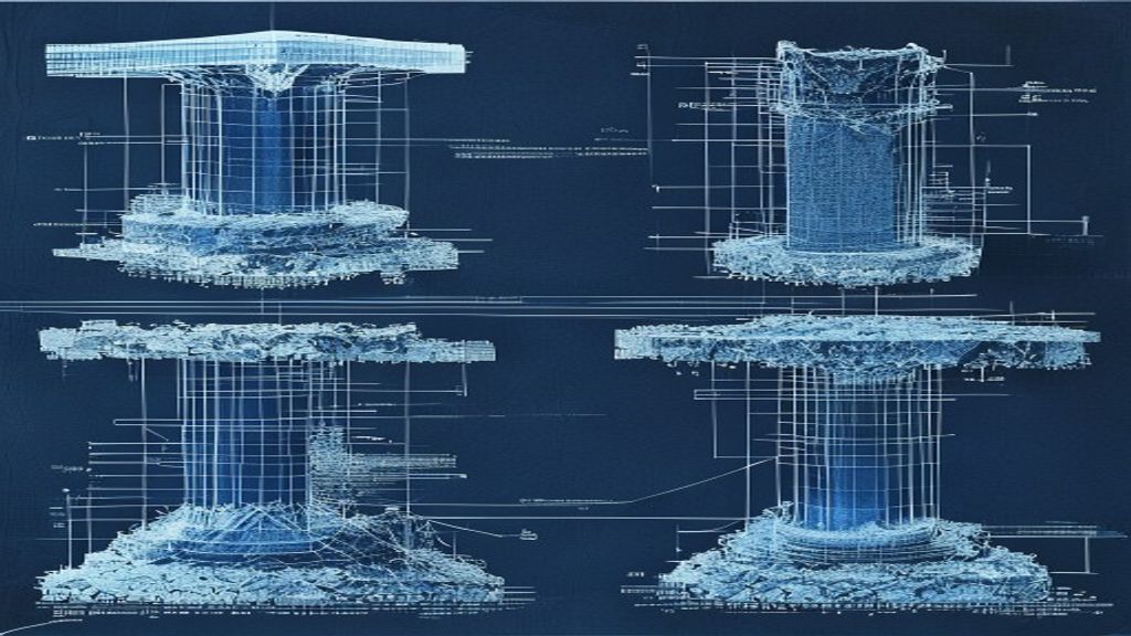
Raft engineering is significantly more complex than isolated footings. The slab must be designed to span between high-load zones under columns and low-load zones in the spans between, experiencing both hogging (negative) and sagging (positive) bending moments across its plan. Finite element analysis (FEA) is the standard tool for raft design on non-uniform soil, with the ground modelled as a spring bed using subgrade reaction modulus values derived from the geotechnical report. TechVisionEra's team uses parametric FEA models linked to the BIM environment, allowing settlement predictions and slab reinforcement to be updated dynamically as soil data or building loads are refined — eliminating the iterative disconnects between structural and geotechnical design that waste time and budget on conventionally managed projects.
Pile Foundations — Transferring Loads to Deep, Competent Strata
When surface soils are too weak to support the structure regardless of footing size — or when groundwater levels, liquefaction risk, or deep compressible layers make shallow foundations unviable — pile foundations bypass the problematic zone entirely. Long, slender structural elements transfer loads down through the weak material to deep, competent strata capable of carrying the imposed load. Pile foundations are the standard engineering solution for high-rise buildings, bridges, marine and port structures, and any project where the geotechnical report identifies inadequate near-surface bearing capacity.
Piles are classified by their load transfer mechanism. End-bearing piles transfer load directly into a hard stratum — rock, dense gravel, or heavily over-consolidated clay — at their toe. Friction piles develop capacity along the shaft surface through interface friction between the pile and the surrounding soil. In practice, most piles combine both mechanisms. The most common pile types used in MENA region projects include:
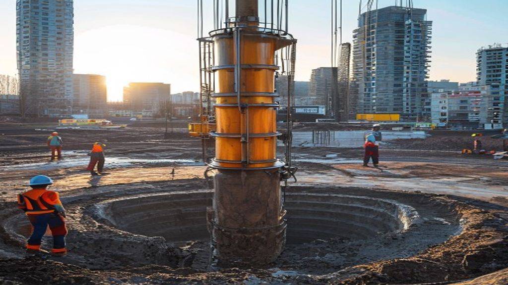
- Bored cast-in-place piles (drilled shafts): Drilled with a rotary rig, reinforced with a steel cage, and concreted in-situ. Low vibration, large diameters achievable up to 2,500 mm. The preferred choice for urban sites near sensitive adjacent structures.
- Driven precast concrete piles: Factory-manufactured to high quality standards, driven by hydraulic hammer to refusal. Fast installation and high load capacity, but generates significant vibration and noise — not suitable near existing structures.
- Continuous Flight Auger (CFA) piles: Installed by simultaneously withdrawing a continuous auger while pumping concrete under pressure. Fast, quiet, low vibration — ideal for medium-stiff clays and sandy soils above groundwater.
- Driven steel H-piles: Slender steel sections driven to refusal. High capacity, easy to splice for greater depths, widely used for bridge abutments and industrial plant. Require corrosion protection in aggressive ground conditions.
- Mini-piles (micro-piles): Small-diameter grouted piles (75–300 mm) for restricted access sites, underpinning of existing structures, and heritage building strengthening where conventional rigs cannot operate.
Pile design must address both axial capacity (vertical load from the structure) and lateral capacity (horizontal forces from wind, seismic action, or earth pressure on basement walls). In tall buildings subject to significant lateral loading, pile-soil lateral interaction and the behaviour of the pile group as a whole are critical design considerations. A pile cap — a thick reinforced concrete block connecting the pile heads to the column above — transfers column loads into the pile group and must itself be carefully designed for punching shear, bending, and the complex strut-and-tie force paths within its depth. TechVisionEra has delivered pile foundation packages for multi-storey towers, industrial plant, and infrastructure projects across challenging ground conditions throughout the MENA region, fully coordinating pile designs with MEP underground services and architectural basement layouts through integrated BIM models.
Comparing Foundation Types: A Decision Framework
Choosing between the four foundation systems requires a structured evaluation of ground conditions, structural load configuration, programme constraints, and budget. The following framework summarises the primary selection criteria applied by TechVisionEra's geotechnical and structural engineers on every new project:
- Bearing capacity above 100 kN/m², column grid structure, well-spaced columns: Pad (isolated) foundations — most economical, fastest to construct, minimum material volume.
- Bearing capacity 75–100 kN/m², load-bearing wall or masonry structure: Strip foundations — simple design, proven performance, low material cost for wall-based structures.
- Bearing capacity below 75 kN/m², variable ground, high groundwater, basement required: Raft foundation — maximum load distribution, provides integral waterproof slab, simplifies coordination of underground MEP services.
- Weak near-surface soils at any depth, very high loads, seismic liquefaction risk, marine or bridge structures: Pile foundations — bypass weak zones, transfer directly to competent strata, handle significant lateral loads.
- Variable ground conditions across the footprint — some areas weak, some competent: Combined piled raft or mixed foundation system — designed to equalise differential settlement and optimise total cost.
- Restricted site access, underpinning of existing structure, or heritage building: Mini-piles or micro-piles — low-headroom equipment, minimal vibration, high-precision installation.
Construction programme and local contractor capability also influence the selection. Driven piles are fast to install but require specialised equipment and generate vibration unsuitable near sensitive neighbours. Bored piles are slower but quieter and better suited to urban environments. Raft slabs require careful curing in hot climates to control thermal cracking from large pour volumes. Strip and pad foundations can typically be executed by any competent local contractor with standard equipment. These practical realities must be factored into the foundation selection alongside structural and geotechnical considerations — a point that purely theoretical foundation comparisons consistently overlook.
Always commission a full geotechnical investigation — at minimum one borehole per 200–400 m² of footprint to a depth of at least 1.5× the anticipated pile length, or 3× the foundation width below the founding level for shallow foundations — before selecting a foundation type. Under-investigating the ground is the single most common cause of foundation cost overruns and redesign iterations on MENA region projects. A geotechnical investigation costing $5,000–15,000 routinely prevents foundation redesigns that cost ten to forty times more in contractor variations and programme delays.
BIM-Driven Foundation Design: TechVisionEra's Integrated Approach
Foundation design does not exist in isolation — it is the first and most consequential link in a chain of coordinated decisions that extends upward through the superstructure, MEP services, and architectural envelope. At TechVisionEra Engineering, foundation models are built within the same Revit environment as the superstructural frame from project inception, enabling automated clash detection between pile caps and underground drainage networks, coordination of ground beam levels with basement MEP service routes, and real-time updating of structural schedules whenever geotechnical recommendations are revised during the design process.
Our structural engineering team collaborates from the earliest design stages with MEP engineers to ensure that underground service entries, drainage runs, electrical duct banks, and mechanical plant pits are fully coordinated with the foundation layout before a single cubic metre of excavation begins. This multidisciplinary BIM-first approach eliminates the costly clashes and unplanned redesign cycles that afflict projects where foundations, services, and superstructure are developed in separate design silos. For projects involving significant interior or fit-out works, our architectural team and interior design specialists are briefed on foundation constraints early — ensuring basement ceiling heights, column positions, and floor-to-floor dimensions are fully aligned from concept through to construction supervision.
For international clients requiring remote project delivery, TechVisionEra operates a cloud-based project management and BIM collaboration platform. Foundation drawings, geotechnical reports, structural calculations, and IFC-compliant coordinated models are shared through a secure Common Data Environment accessible from any location worldwide. Our team has delivered complete foundation design packages — from preliminary feasibility sizing through to tender-ready drawing sets, specification documents, and geotechnical interpretation reports — for projects in Syria, Jordan, Saudi Arabia, the UAE, Qatar, and across North Africa, all coordinated remotely to Eurocode 7 standards. For projects requiring on-site presence during foundation construction, TechVisionEra can deploy resident engineers to inspect excavation conditions, verify encountered soils match geotechnical assumptions, witness static and dynamic pile load tests, and review integrity test results before authorising pile cap construction. Contact our structural team to discuss your foundation engineering requirements.
Key Takeaway
Foundation type selection is driven by soil bearing capacity, structural load configuration, groundwater conditions, and budget — not by convention or habit. Pad foundations suit strong soils with isolated point loads; strip foundations serve load-bearing wall structures efficiently; raft foundations solve weak or variable ground conditions and waterproofing requirements simultaneously; pile foundations reach deep competent strata when surface soils cannot carry the structural load. TechVisionEra Engineering delivers all four foundation systems with full Eurocode 7 compliance, integrated BIM coordination, and remote delivery capability for international clients across the MENA region and beyond.
Frequently Asked Questions
A pad (isolated) foundation supports a single column with an individual concrete footing beneath each column base. A raft foundation is a single reinforced concrete slab that extends beneath the entire building footprint, connecting all columns and walls into one continuous plate. Pad foundations are more economical on strong soils where columns are widely spaced. Raft foundations are used when soil bearing capacity is low (typically below 75 kN/m²), when individual pad footings would overlap, or when a continuous waterproof slab is required for basement construction. The raft distributes the building's total load over the maximum possible ground area, reducing bearing pressure per unit area by a factor of three or more compared to isolated pads on the same footprint.
Pile foundations are required when near-surface soils cannot safely carry the structural load regardless of footing size, when deep compressible layers (such as soft clay, peat, or loose fill) would cause excessive settlement under shallow foundations, when groundwater conditions make shallow excavation impractical, when there is a seismic liquefaction risk in the upper soil layers, or when very high column loads demand load transfer to deep, dense strata such as rock or gravel. Pile foundations are also standard for marine and offshore structures, bridge abutments and piers, and any structure where differential settlement limits are very tight and surface soils are variable. The geotechnical report's recommended allowable bearing capacity is the primary trigger: if a shallow foundation of practical size cannot keep bearing pressure within safe limits, piles are required.
Pile foundations are the most expensive foundation system, typically costing two to five times more per column load than equivalent shallow foundations on good ground. The cost premium is driven by rig mobilisation, specialist drilling or driving equipment, concrete and steel for the pile shafts, pile cap construction, and mandatory load testing (static load tests, dynamic pile testing, and integrity testing). However, the cost comparison must always be made against the risk cost of an inappropriate shallow foundation: differential settlement repair, structural remediation, or complete foundation reconstruction after the fact can cost far more than the premium for correct piling at the outset. On ground where piles are genuinely needed, they are consistently the most cost-effective long-term choice.
Foundation design timeline depends on project complexity and geotechnical data availability. For a straightforward low-rise building on uniform soil with an existing geotechnical report, preliminary foundation sizing can be completed in 1–2 weeks and construction drawings in 3–4 weeks. For a multi-storey building requiring finite element raft analysis or pile design, the structural design phase typically takes 4–8 weeks from receipt of a complete geotechnical report. Complex projects involving piled rafts, seismic design, or basement waterproofing coordination may take 8–12 weeks. The single largest variable is geotechnical investigation — obtaining a full bore log and laboratory results typically takes 3–6 weeks depending on site access and local laboratory capacity. TechVisionEra Engineering coordinates the full design timeline with clients at project inception and can phase deliverables to support tender or permit applications in parallel with detailed design.
At a minimum, foundation design requires a geotechnical investigation report covering: borehole drilling or trial pits (at least one borehole per 200–400 m² of building footprint for simple structures, more for complex or high-rise projects), Standard Penetration Tests (SPTs) at regular depth intervals, undisturbed soil samples for laboratory testing, groundwater level measurements, and laboratory analysis covering moisture content, Atterberg limits, particle size distribution, shear strength (undrained or drained as appropriate), and consolidation characteristics for compressible layers. For pile projects, a minimum borehole depth of 1.5× the anticipated pile length is required. For sites with potential contamination, seismicity, or problematic soils (expansive clays, collapsible soils, karst limestone), additional specialist investigations are needed. TechVisionEra can advise on the appropriate scope of geotechnical investigation for any project and review geotechnical reports on behalf of clients before foundation design begins.
Yes. TechVisionEra Engineering has delivered complete foundation design packages remotely for projects across Syria, Jordan, Saudi Arabia, the UAE, Qatar, and North Africa. Our remote delivery workflow includes: geotechnical report review and interpretation, structural foundation design to Eurocode 7 (and local code supplements), full BIM coordination in Revit, and delivery of IFC models, DWG drawings, PDF drawing sets, and structural calculation reports through a secure cloud-based Common Data Environment. We conduct design review meetings via video conference, share models through BIM collaboration platforms, and respond to construction queries in real time. For on-site phases such as foundation inspection, pile testing witness, and geotechnical verification during excavation, we can coordinate with local specialist partners or deploy a TechVisionEra resident engineer. Contact us with your project brief and geotechnical report to receive a remote delivery proposal.
Eurocode 7 (EN 1997) is a rigorous limit state design framework that requires explicit calculation of both ultimate and serviceability limit states, application of partial safety factors to soil parameters and structural loads, and a comprehensive treatment of ground uncertainty through three Design Approaches (DA1, DA2, DA3). Many local codes in the MENA region — including older Syrian, Iraqi, and Libyan standards — were derived from allowable stress design (ASD) methodologies that apply a single global factor of safety to the ultimate bearing capacity. The practical implications are: Eurocode 7 typically produces more reliable, transparent designs but requires more detailed geotechnical input data; ASD codes are simpler to apply with less data but can either over- or under-design depending on assumed safety factors. TechVisionEra applies Eurocode 7 as the primary design standard on all international projects, with local code compliance checks performed as a secondary verification where required by the project authority.
Differential settlement is the difference in vertical movement between two points on a building's foundation — for example, one corner settling 30 mm while the adjacent corner settles only 10 mm. The differential (20 mm in this case) induces angular distortion in the structure, causing cracking in rigid elements like masonry walls and finishes, doors and windows that jam in their frames, and in severe cases, structural damage to the frame itself. Allowable differential settlement limits under Eurocode 7 range from approximately 1/500 of the column spacing for sensitive structures to 1/150 for robust industrial frames. Foundation design controls differential settlement by: choosing a foundation type that minimises variation (raft foundations inherently equalise settlement better than isolated pads on variable ground), sizing footings to produce equal bearing pressure under each element, using ground improvement techniques to homogenise variable soils, and designing the superstructure frame with sufficient stiffness to redistribute forces safely if some settlement occurs.
In TechVisionEra's BIM workflow, foundation models and MEP underground service models are developed within the same federated Revit model environment from the earliest design stages. Automated clash detection identifies conflicts between pile caps and drainage manholes, between ground beams and electrical duct banks, between raft slab penetrations and incoming service connections, and between pile locations and underground fuel or water storage tanks. Clash reports are reviewed in regular multidisciplinary coordination meetings, and modifications are made to the lowest-cost element — typically adjusting service routing rather than structural elements, unless a structural modification is clearly more economical. This coordination process, conducted before construction begins, eliminates the costly site variations and programme delays that result from discovering underground clashes during excavation. For complex basement projects, TechVisionEra produces a coordinated underground services and foundation layout drawing that serves as the primary reference for all subcontractors.
Bored cast-in-place piles (also called drilled shafts or rotary bored piles) are almost always the preferred choice for urban sites close to existing structures. The rotary drilling process generates minimal vibration and no dynamic impact loads — unlike driven piles which can damage adjacent foundations, cause settlement in loose sands through vibration, and disturb sensitive building occupants. Continuous Flight Auger (CFA) piles are also low-vibration and can be a faster and more economical alternative to full rotary boring in suitable soil conditions (medium-stiff clays and sands above groundwater). Driven precast concrete or steel piles should generally be avoided within 15–25 m of sensitive structures without a specialist vibration impact assessment, and are prohibited near hospitals, historical buildings, or structures with vibration-sensitive equipment. TechVisionEra specifies vibration monitoring as standard practice during pile installation on urban sites, with defined threshold values that trigger work stoppage and review if exceeded.
Pile testing requirements are governed by Eurocode 7 Annex A and project-specific specifications. The main test types are: Static Load Tests (SLTs) — a direct measurement of pile capacity by loading the pile to typically 1.5–2.0× the working load using kentledge or reaction piles, measuring settlement against load; Dynamic Load Tests (DLTs) using the Pile Driving Analyser (PDA) — a faster and less expensive alternative to SLTs, applicable to driven piles and sometimes bored piles through the high-strain dynamic testing method; Sonic Integrity Tests (SIT), also called Pile Integrity Tests (PIT) — a low-strain dynamic test that checks for shaft defects such as cracks, inclusions, or cross-section reductions; and Cross-Hole Sonic Logging (CSL) — installed in large-diameter bored piles with pre-installed access tubes for comprehensive shaft integrity checking. Minimum test quantities under Eurocode 7 are typically 1% of production piles for static load tests and 5–10% for integrity tests, but project specifications often require more. TechVisionEra's pile specifications include a full testing programme tailored to pile type, diameter, installation method, and ground conditions.
Yes. Foundation strengthening — also called foundation underpinning — is a specialist area of structural engineering used when existing foundations are inadequate for new loads (e.g., adding storeys to an existing building), when original foundations were poorly designed and settlement or cracking has occurred, when ground conditions have changed (e.g., groundwater level change, adjacent excavation, tree root damage to clay soils), or when a change of use increases floor loads beyond the original design. Common underpinning methods include: traditional mass concrete underpinning (sequential deepening beneath the existing footing), mini-pile underpinning (installing small-diameter high-pressure grouted piles through or adjacent to the existing footings), and jet grouting (injecting cementitious grout under pressure to create soil-cement columns beneath the foundation). TechVisionEra's structural team has experience in assessment and redesign of existing foundations for building extension and upgrade projects, including survey of existing ground conditions and load path analysis through the existing structure.
A piled raft (or raft on piles) is a hybrid foundation system that combines a reinforced concrete raft slab with pile elements beneath it. The raft alone would be too lightly loaded to cause failure, but the expected settlement would exceed acceptable limits; the piles reduce settlement without needing to carry the full structural load. Piled rafts are also used when a small number of heavily-loaded columns would cause the raft to punch through the ground, while the remainder of the raft performs adequately without piles. The design challenge is the interaction between the raft, the piles, and the ground — a three-way system requiring sophisticated finite element analysis to determine load sharing between the slab and the piles. Piled rafts are common beneath high-rise towers on medium-strength soils, beneath large industrial tank farms, and on heterogeneous ground where uniform settlement is critical. TechVisionEra's structural team performs piled raft design using coupled structural-geotechnical FEA with non-linear soil models.
Seismic design introduces three major foundation-related concerns beyond static load requirements. First, soil liquefaction risk: saturated loose sands and silts can lose their bearing capacity entirely during strong ground shaking, transforming temporarily into a fluid-like state. In liquefaction-susceptible zones, pile foundations driven through the liquefiable layer to competent strata below are typically required; shallow foundations on liquefiable soil are not acceptable. Second, foundation overturning resistance: seismic lateral forces create overturning moments at the base of structures that can cause net uplift on windward foundations — shallow pad footings may need to be enlarged, tied together, or replaced with piles designed to resist tension as well as compression. Third, foundation stiffness and mass effects on building dynamic response: a stiffer, more massive foundation system shifts the building's natural frequency, which may increase or decrease seismic forces depending on the ground's frequency content. Eurocode 8 (EN 1998) provides detailed requirements for foundation design in seismic zones, including specific tie beam requirements, capacity design principles, and geotechnical category assessments that TechVisionEra applies on all projects in seismically active regions including Syria, Turkey, and the northern Arabian Peninsula.
TechVisionEra Engineering's standard foundation design deliverable package includes: a Foundation Design Basis Report summarising geotechnical parameters, design standards applied, load assumptions, and design methodology; foundation general arrangement drawings showing the layout, dimensions, levels, and setting-out coordinates of all foundation elements; reinforcement drawings with bar bending schedules for all reinforced concrete elements (pile caps, grade beams, raft slabs, pad and strip footings); structural calculations covering bearing capacity checks, settlement analysis, reinforcement design, and punching shear verification; a pile specification (for piled projects) covering pile type, installation method, concrete mix, reinforcement, and testing requirements; coordination drawings showing foundation layout overlaid with MEP underground services; and a BIM model in Revit (native) and IFC (open standard) formats for construction coordination. For projects requiring local authority submission, we also provide translated or locally code-compliant calculation reports. All deliverables are issued through our project document management system with full revision control and audit trail.
Foundation design for projects in Syria and the wider MENA region must account for several region-specific factors. Soil conditions in Syria range from competent limestone and basalt rock in the western mountains and central plateau, to soft alluvial deposits in river valleys, to wind-blown sandy soils in the east — requiring site-specific geotechnical investigation rather than generic assumptions. Seismic hazard is significant in northwestern Syria (close to the East Anatolian Fault System), requiring seismic foundation design to Eurocode 8 principles with liquefaction assessment where waterlogged alluvial soils are present. Expansive clay soils in the semi-arid central and northern regions require deep foundations below the seasonal moisture variation zone. For war-damaged structures requiring reconstruction, TechVisionEra performs structural condition surveys to assess existing foundation integrity before designing extensions or additional storeys. TechVisionEra's team has specific experience delivering foundation designs remotely for Syrian reconstruction projects and can coordinate with local civil engineering contractors to ensure construction-ready documentation matches local equipment availability and construction practice.